Background
On wire winders, bottle-cap cappers, binding machines, and surgical instruments, the drive train doesn’t need “maximum torque transfer” — it needs “constant output torque regardless of speed”. Friction discs drift after wear. Electromagnetic clutches need drive current and run hot. Permanent-magnet hysteresis clutches generate torque from the relative motion between a permanent magnetic field and a hysteresis material — no contact, no wear, no power supply. They are the simplest, most reliable solution for constant-torque control.
How it works
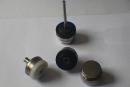
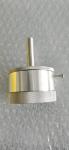
The working section is a permanent-magnet rotor and a hysteresis cup. As they rotate relative to each other, the cup is repeatedly magnetised and demagnetised; the area enclosed by the hysteresis loop is dissipated as heat, while a reaction torque independent of speed is produced. From 1 rpm to 1000 rpm, output torque is essentially unchanged; brief overloads simply slip without damaging the clutch. Torque is set by hysteresis material volume and air-gap field strength — adjusting the gap provides about ±20% trim.
Application notes
Wire production lines: a hysteresis clutch in series with the take-up spindle keeps tension steady across the entire diameter range, preventing fine-wire breakage and coarse-wire pile-up. Bottle capping: placed between the capping head and the pneumatic drive, it slips when torque exceeds the setpoint, sparing the bottle threads. Surgical instruments: used for torque-limited handles meeting bone-screw torque specs. Note that hysteresis clutches are thermal-balance devices — sustained slip generates heat, so verify slip power stays within the rated dissipation envelope.
Selection guide
Three-step method: (1) determine process torque T_w and allowed range ±ΔT; (2) compute maximum slip power P = 2π × n_slip × T and confirm it falls within the product’s thermal curve; (3) decide on mounting — through-bore shaft type, or flange-suspended type. Horus standard models cover 0.05–50 N·m, run bidirectionally, and include constant-power variants for winding tension that varies with roll diameter.